
Triple-track MSR decoding
Reads up to 3 magnetic-stripe tracks at once and recovers real-world card data reliably from difficult head signals.
Secure MagStripe Decoding ASIC
A 5mm x 5mm, 36-pin triple-track MSR decoding ASIC that combines magnetic-stripe reading, TDES encryption, DUKPT key management, and PCI SRED tamper protection in one component.
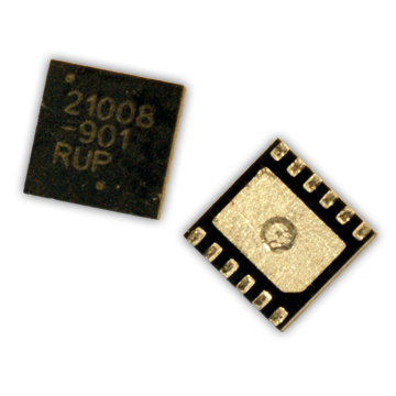
TriMag IV is ID TECH's MSR decoding ASIC in a 5mm x 5mm, 36-pin package. It integrates magnetic-stripe reading with a triple DES encryption engine, physical security protection hardware, and a UART/SPI interface. When it receives the magnetic head signals, card data is recovered, encrypted, and passed to the external interface over UART or SPI. The chip reads up to 3 tracks at the same time, and its signal processing recovers F2F-encoded data reliably even with wide swings in signal amplitude, bit interval, and bit position.
Reads up to 3 magnetic-stripe tracks at once and recovers real-world card data reliably from difficult head signals.
A built-in triple DES engine encrypts incoming MSR data, with advanced DUKPT key management and a hardware random number generator.
Incoming MSR data is encrypted by the built-in triple DES engine with DUKPT key management and a hardware random number generator. On-chip physical tamper, over/under voltage, and over/under temperature detectors provide PCI SRED-compliant protection against attacks.
A 32 MHz 32-bit core with 96 KB of code space, 6 KB of RAM, built-in EEPROM, and a real-time clock.
UART and SPI host interfaces, plus an EMV-compliant ISO 7816 smart card interface, a bar code reader interface, and a mobile phone audio jack interface with a micro-power signal detector. 13 GPIO at 4mA and 3 GPIO at 12mA can drive LED indicators and a beeper directly.
Sleep mode at 35 µA, shutdown with tamper on under 3 µA, and battery ship mode under 2 µA.
| Specification | TriMag IV | TriMag III |
|---|---|---|
| Size | 5mm x 5mm | 6mm x 6mm |
| Additional input reading | EMV smart card and bar code reader | EMV smart card and bar code reader |
| Hardware encryption engine | Yes | Yes |
| Interfaces | SPI and UART | SPI, UART, and USB |
| PCI SRED security features | On-chip physical tamper, over/under voltage, over/under temperature detectors | No |
| Mobile phone audio jack interface | Yes | No |
| Random number generator | Yes | No |
| Real-time clock | Yes | No |
| MCU | 32 MHz 32-bit ARM Cortex-M0 | 12 MHz 8-bit 8051 |
| Code space | 96 KB | 64 KB |
| RAM space | 6 KB | 4 KB |
| Built-in EEPROM | Yes | No |
| Low power modes | Sleep 35 µA; shutdown with tamper on <3 µA; battery ship <2 µA | Sleep <150 µA |
| Symbol | Parameter | Min | Typ | Max | Units |
|---|---|---|---|---|---|
| VDD3 | 3.3V DC Supply | 2.5 | 3.6 | V | |
| VBAT | 3.3V Battery Supply | 2.5 | 3.7 | V | |
| Idd32M | CPU working current @ 32 MHz | 12.92 | mA | ||
| Idd8m | CPU working current @ 8 MHz | 4.09 | mA | ||
| Idd4m | CPU working current @ 4 MHz | 2.43 | mA | ||
| IddMSR | 3 Track MSR decode current @ 1M | 1.5 | mA | ||
| Iddslp2 | Sleep Mode (50 kHz) | 30 | µA | ||
| Iddsld1 | Shut Down Current with Tamper on | 2 | µA | ||
| Iddsld2 | Power Down Keep Code | 1 | µA | ||
| Iddbat | Battery ship mode current | 1 | µA | ||
| VSS | Analog/Digital Ground | 0 | V | ||
| Ta | Ambient Temperature | -40 | 85 | °C | |
| Tj | Junction Temperature | -40 | 90 | °C |
| Pin # | Name | Pad Description |
|---|---|---|
| 1 | HDA1 | Magnetic head input 1 (+) track A |
| 2 | HDA2 | Magnetic head input 2 (-) track A |
| 3 | HDB1 | Magnetic head input 1 (+) track B |
| 4 | HDB2 | Magnetic head input 2 (-) track B |
| 5 | HDC1 | Magnetic head input 1 (+) track C |
| 6 | HDC2 | Magnetic head input 2 (-) track C |
| 7 | VSS | Ground pin |
| 8 | TAMP_IN | Tamper in |
| 9 | VDD18 | 1.8V supply for digital. External decoupling capacitor for internal 1.8V regulator |
| 10 | VBAT | 3.0V battery voltage used for “battery ship” mode. |
| 11 | VDD3 | 3.3V power pin. |
| 12 | COMP | Micro Power Signal Detector |
| 13 | RESETN | External reset in. Active low. This will power down all of the analog, digital, and power management. |
| 14 | TX | TXD for UART0. Alternative function is GPIO11 |
| 15 | RX | RXD for UART0. Alternative function is GPIO10. (Also connect to WIC) |
| 16 | LEDG | Green LED, 8mA GPIO3, Compare0 output |
| 17 | LEDR | Red LED, 8mA GPIO4, Compare1 output |
| 18 | BEEP | Beep, 8mA GPIO5, Compare2 output |
| 19 | TCNT | Timer Count, 4mA GPIO6 |
| 20 | TCAP | Capture Input, 4mA GPIO7 |
| 21 | GPIO0 | General Purpose, 4mA GPIO0 (Also connect to WIC via NMI) |
| 22 | GPIO1 | General Purpose, 4mA GPIO1 |
| 23 | VSS | Ground pin |
| 24 | TEST | TEST mode input |
| 25 | SPCLK | SPI Clock. Alternative function is GPIO12 |
| 26 | MOSI | SPI data (Master Out/Slave In). Alternative function is GPIO13 |
| 27 | MISO | SPI data (Master In/Slave Out). Alternative function is GPIO14 |
| 28 | NCS | SPI chip select not. Alternative function is GPIO15. (Also connect to WIC) |
| 29 | GPIO2 | General Purpose, 4mA GPIO2 |
| 30 | SWDIO | Serial Wire Data |
| 31 | SWCLK | Serial Wire Clock. |
| 32 | SMIO | UART1 RXD/TXD for Smart Card I/O. Alternative function is GPIO9. |
| 33 | SMCLK | Output clock for Smart Card. Alternative function is GPIO8 |
| 34 | TAMP_OUT | Tamper out |
| 35 | XTL_IN | 32K Crystal Input |
| 36 | XTL_OUT | 32K Crystal Output |
Tell us about your environment and our team will follow up.